



 Search...
 English
How to Choose a Durable Dustbin Injection Mold for Mass Production
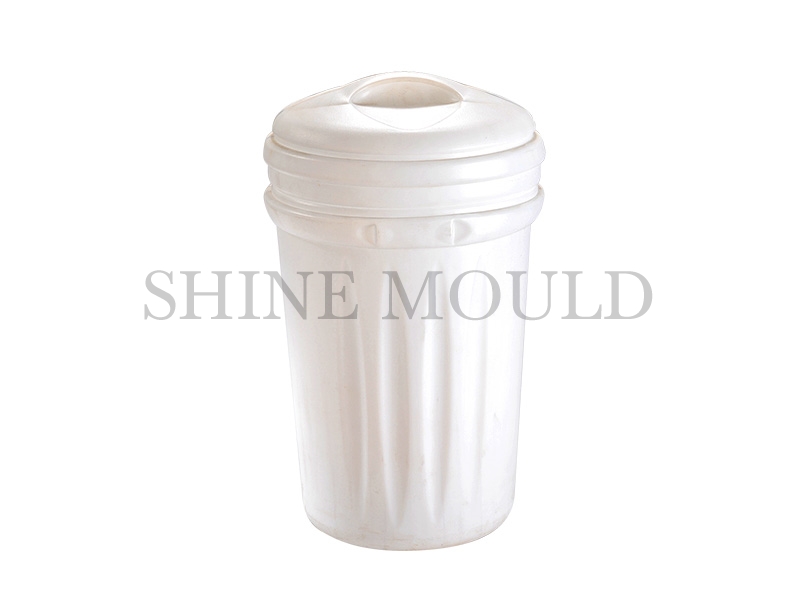
Material selection has a direct influence on how a large plastic dustbin behaves during injection molding. HDPE and PP are both used for containers and household products, yet their processing behavior is not identical. Differences in stiffness, toughness, shrinkage, and melt flow can affect cavity filling, cooling, and final shape.
A dustbin usually combines broad wall areas with openings, reinforced sections, and a relatively deep interior. Such geometry places different demands on the material as it moves through the cavity. A mold designed around one material may need structural adjustments when production changes to another.
HDPE can provide a useful balance between toughness and rigidity, while PP can offer a different combination of stiffness and resistance to repeated handling. The actual result depends on grade, wall design, processing conditions, and mold temperature control. Treating the material as an isolated choice can make mold development more difficult.
Several areas deserve attention during the initial design stage:
- Wall thickness should remain reasonably consistent where the product structure allows.
- Changes in thickness need enough space for material to flow and cool.
- Rounded transitions can reduce abrupt changes in the mold cavity.
- Reinforced areas should support the product without creating excessive local thickness.
- The cavity layout should match the intended material and production method.
Shrinkage also needs consideration. Plastic contracts as it cools, and different sections of a dustbin may cool at different rates. A large flat wall can respond differently from a reinforced bottom or rim. Mold dimensions therefore need to account for the behavior expected from the selected material.
Material properties also influence the choice of mold components. Areas exposed to repeated pressure, friction, or thermal changes need suitable structural support. A durable mold is not simply a strong metal structure; its geometry, material behavior, cooling arrangement, and ejection system need to work together.
How Should the Mold Structure Match Dustbin Geometry
A dustbin has a relatively simple appearance, but the cavity can contain several areas with different molding requirements. The side walls, base, upper rim, reinforcing ribs, and handle‑related sections may all experience different forces during filling and ejection.
Large wall surfaces deserve particular attention. If the cavity allows material to fill unevenly, some areas may receive pressure earlier than others. Such differences can contribute to uneven shrinkage or visible deformation after cooling.
A practical structural approach considers the product from several directions:
- Wall design: Broad walls should avoid unnecessary thickness changes. Gradual transitions can make filling and cooling more consistent.
- Bottom structure: The base needs enough structural support for repeated handling. Reinforcing features can add stiffness, although excessive material concentration can create local cooling differences.
- Rim area: The upper edge often needs additional rigidity because it may interact with lids, handles, stacking arrangements, or other components.
- Corner areas: Sharp internal transitions can create stress concentration and may complicate material flow. Rounded cavity transitions can provide a smoother structural change.
The opening direction of the mold also affects the design. The product needs enough clearance to separate from the cavity without damaging the walls or reinforced areas. If the geometry creates areas that hold the product tightly against the mold, the ejection system may require additional consideration.
A well‑planned Dustbin Injection Mold should also allow practical access for inspection and maintenance. Cooling channels, ejector components, and cavity surfaces become easier to service when their arrangement has been considered during the structural design stage rather than added as an afterthought.
What Mold Features Support Consistent Material Flow
Material flow becomes more difficult when a product has a large cavity combined with different wall sections. The position and arrangement of the material entry points can influence how evenly the cavity fills.
For HDPE and PP, flow behavior changes according to material grade and processing conditions. A mold intended for one material should not automatically be assumed to behave in the same way with another. The cavity geometry, entry position, and flow distance all contribute to the filling pattern.
A balanced flow path can help reduce differences between sections of the product. When material reaches one region much earlier than another, temperature and pressure conditions may differ across the cavity. The resulting product can show variations in surface appearance, shrinkage, or shape.
Several design considerations can help maintain a more controlled filling process:
- Keep flow paths appropriate for the cavity geometry.
- Avoid unnecessary changes in wall thickness.
- Position material entry areas with the full product shape in mind.
- Consider reinforced sections when assessing flow resistance.
- Allow sufficient space around functional openings and structural features.
Large dustbins also benefit from careful consideration of where material flow changes direction. Corners, ribs, and transitions can alter the movement of molten plastic. If several features meet in a small area, local filling conditions can become less predictable.
| Mold Area | Main Design Concern | Possible Production Effect |
|---|---|---|
| Side Wall | Consistent filling and cooling | Shape stability |
| Bottom | Material concentration and support | Base deformation |
| Upper Rim | Structural rigidity | Edge consistency |
| Reinforcing Rib | Local thickness | Cooling variation |
| Corner Transition | Smooth material movement | Reduced molding stress |
Flow design is closely connected to cooling. A section that fills differently may also cool differently, making the two systems difficult to separate during mold development. For that reason, material movement should be considered alongside temperature control rather than treated as an independent stage.
How Does the Cooling System Affect Mold Efficiency
Cooling has a strong influence on both molding rhythm and product shape. Once the plastic enters the cavity, heat must move away from the material before the dustbin can be released without excessive deformation.
The challenge becomes more noticeable with broad walls and deep cavity areas. A section close to a cooling channel may lose heat at a different rate from another section farther away. When the temperature difference becomes uneven across the product, shrinkage can also vary.
Cooling channel placement should follow the geometry of the dustbin rather than simply filling available space inside the mold base. The side walls, bottom, rim, and reinforced areas each have different thermal requirements.
For HDPE and PP, cooling design should consider:
- Material shrinkage behavior
- Wall thickness distribution
- Distance between the cavity surface and cooling passages
- Areas with concentrated material
- Expected product deformation during cooling
The bottom section often needs special attention because reinforcing features can create thicker regions. If heat remains in those areas longer than in the surrounding wall, the base may respond differently during cooling.
Cooling also affects cycle consistency. A mold that removes heat unevenly can produce changes from one production run to another, even when the basic injection conditions remain similar. Stable temperature control supports more predictable release and reduces unnecessary adjustment during batch production.
For a Dustbin Mould Supplier, cooling design is therefore part of the structural discussion rather than a separate utility detail. Product geometry, selected plastic, cavity layout, and cooling arrangement need to be evaluated together when preparing a mold for repeated production.
Which Ejection Method Fits Different Dustbin Structures
Ejection takes place once the molded plastic has cooled enough to separate cleanly from the cavity. A dustbin with broad wall sections and considerable depth requires a release process that spreads force across multiple areas rather than concentrating it at a single point. Concentrated pressure tends to leave marks or cause local deformation, particularly near thinner wall sections where the material has less resistance to push‑back.
Product geometry largely dictates how the ejection system gets arranged. Flat panel areas often call for several evenly spaced pushing points, while ribbed or reinforced sections offer sturdier locations for applying force without risking surface damage. The placement of ribs, corner transitions, and the bottom structure further narrows down where ejection components can realistically be positioned.
A few approaches suit different geometries:
- Ejector pins — apply force at specific points where the wall has enough structural backing to resist localized stress.
- Ejector plates — distribute contact across a wider area, useful when a single concentrated push point would risk marking the surface.
- Combined arrangements — pair pins and plates when a dustbin includes both flat panels and reinforced zones that behave differently during release.
Contact area between the molded part and the cavity surface plays into this as well. A deep‑walled dustbin with substantial internal surface area generates more friction during separation, which can slow release or increase the force needed to push the part free.
Draft angle ties directly into the same problem. Adequate clearance lets the wall pull away from the cavity with minimal resistance. Where that angle falls short, the ejection system compensates with added force, and that added force raises the likelihood of visible marks or minor distortion on the finished part.
How Can Mold Design Improve Dustbin Strength
A dustbin needs to hold up through lifting, dragging across pavement, tipping during emptying, and stacking in storage. That kind of durability comes from the combination of material choice and structural layout — wall thickness by itself rarely accounts for it.
The base carries its own set of demands. Repeated ground contact wears at the bottom surface, and a fully loaded container transfers considerable downward force through that same area. Distributing that load across a well‑balanced bottom structure — rather than concentrating it at a few contact points — tends to hold up better over repeated use.
The rim serves a comparable structural role at the opposite end of the part. A reinforced upper edge keeps the opening from deforming and provides a stable anchor point for handles or a lid connection. Abrupt jumps in wall thickness near the rim still need to be avoided, since uneven cooling in that zone can compromise dimensional accuracy.
Material grade shapes some of these structural decisions. HDPE and PP respond differently under the same loading conditions, so a design built around one material's flexibility may not translate directly to the other without adjustment. Mold development benefits from settling on the intended balance between impact resistance, stiffness, and resistance to deformation before finalizing wall and rib geometry.
Worth reviewing during structural design:
- Wall thickness consistency across the part
- Rib placement and cross‑sectional thickness
- Bottom support geometry
- Corner and transition radii
- Rim rigidity
- Handle attachment points
- Areas where material concentration builds up unintentionally
A Dustbin Injection Mold built around these considerations produces more consistent geometry run after run. Even a dustbin that looks straightforward on paper depends on this relationship between cavity shape and how the chosen material actually behaves under heat and pressure.
What Should Manufacturers Check Before Mass Production
A mold can look mechanically sound on the bench and still need adjustment before it's ready for continuous production. Trial runs reveal how filling, cooling, ejection, and final part geometry interact once the mold is actually cycling under real conditions — something a static inspection can't fully predict.
Initial checks should cover the entire molding sequence, not just how the finished part looks. A dustbin can appear acceptable on the surface while still carrying uneven wall thickness, sluggish release, or dimensional drift that only becomes obvious after the part cools fully.
- Cavity filling — material needs to reach every section of the cavity without short shots or excess buildup pooling in specific areas.
- Cooling behavior — different wall zones should cool at a reasonably even pace, with particular attention paid to the bottom, rib areas, and rim.
- Ejection movement — the part should separate from the cavity without excessive drag, visible pin marks, or distortion introduced during release.
- Product geometry — the opening, side walls, base, and any reinforced zones should hold their intended shape once fully cooled.
- Mold condition — cavity surfaces, cooling channels, sealing faces, and moving components need to stay accessible for inspection and routine cleaning.
Working with a Dustbin Mould Supplier goes more smoothly when technical details are laid out clearly from the start. Product drawings, material selection, intended production volume, wall structure, ejection requirements, and cooling layout all give both sides a shared reference point during development.
Switching material — HDPE to PP or the reverse — often calls for reassessing mold conditions even when the cavity geometry stays the same. Flow characteristics, shrinkage rates, cooling response, and how easily the part releases can all shift with a material change, sometimes enough to require mold adjustments.
How Can a Dustbin Injection Mold Support Stable Batch Production
Sustained production puts repeated mechanical and thermal stress on a mold, cycle after cycle. Long‑term stability depends on more than cavity strength alone — it also comes down to how easily cooling channels, ejection components, and moving sections can keep performing their intended function over thousands of cycles.
A well‑built mold allows routine inspection without requiring extensive disassembly each time. Cooling passages need to stay reachable for cleaning and maintenance, and ejection components should sit in positions where wear or misalignment can be caught during a normal servicing pass rather than discovered mid‑production.
Small shifts in part geometry can ripple through the whole process. A slight adjustment to wall shape changes cooling behavior in that zone, and a modified rib can shift where material concentrates during filling. Mold maintenance needs to account for both the functional hardware and the cavity surfaces themselves.
Recurring maintenance points worth building into a batch production schedule:
- Clear material residue from accessible mold surfaces
- Check ejection components for wear or sticking
- Inspect cooling passages for reduced flow or buildup
- Examine cavity edges and reinforced zones for damage
- Keep moving sections clean and properly lubricated
- Track any changes in part deformation or release behavior over time
Material selection remains part of this ongoing assessment. HDPE and PP don't always respond the same way to identical mold conditions, so process settings may need recalibration whenever material grade or formulation changes partway through a production run.
A capable Dustbin Mould Supplier contributes to this process by clarifying maintenance access, expected component replacement intervals, cooling system layout, and ejection design during the development phase — well before the mold reaches full production. Clear communication at that stage cuts down on guesswork once the mold is running continuously.
Stable batch molding ultimately depends on several systems functioning together rather than in isolation. Material behavior governs how the cavity fills, cavity geometry shapes the final part, cooling determines how ready the part is for release, and ejection design decides how cleanly that part separates from the mold. A design that accounts for all four elements together tends to hold up better across a long production run than one that treats them as separate problems.
.jpg)
.jpg)
