



 Search...
 English
What Factors Should Be Considered When Designing a Plastic Crate Mould
Plastic crates hold a distinct position within the broader field of injection moulding. Their size tends to run larger than typical parts, they carry substantial loads, and they face repeated handling in environments that are rarely gentle. Moulds built to produce these parts run into challenges that smaller, less demanding components rarely present.
Scale plays a noticeable role here. Crate moulds are generally heavier and require thicker steel sections along with reinforced support structures compared to moulds built for smaller items. That added weight has downstream effects, influencing which moulding machines and handling equipment can accommodate the tooling.
Structural performance sits at the center of crate mould planning. A finished crate needs to bear weight without noticeable deflection, which means the mould has to produce a part capable of holding its shape under sustained pressure. This requirement threads through nearly every decision in the design process, from steel choice to how cooling channels get arranged.
There's also a balancing act between structural integrity and material efficiency. A crate mould needs to produce parts that hold up structurally without relying on unnecessary plastic volume. How material spreads through the cavity depends heavily on mould geometry, and thoughtful design tends to concentrate strength where it's genuinely needed rather than distributing material evenly out of convenience.
How the Crate's Intended Application Shapes Mould Decisions
The way a crate will be used tends to guide much of the mould's design direction. A crate meant to hold heavy industrial components calls for different structural properties than one intended for lighter consumer goods. Mould design needs to align with whatever performance the final application demands.
Load capacity feeds directly into mould planning. Crates built to carry heavier contents typically need thicker wall sections, added reinforcement, and materials chosen for their load‑bearing characteristics. These requirements show up in the mould itself — deeper cavities, more involved cooling layouts, and ejection systems built to handle a sturdier part.
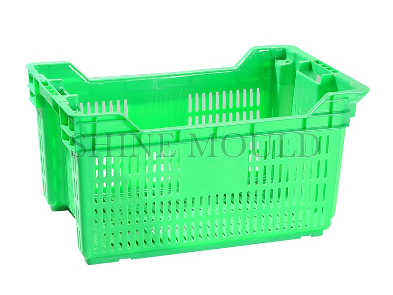
Stacking behavior introduces its own set of complications. Many crates are designed to interlock when stacked full and nest compactly when empty, and these functional features often translate into undercuts and irregular surfaces within the mould. Handles, stacking ribs, and reinforcement points all need attention during the design phase, since each one adds geometric complexity that the mould has to accommodate.
Overall crate dimensions influence mould scale as well. Larger crates call for larger moulds, which then require moulding machines with sufficient capacity to run them. The weight of the finished part also has a bearing on cycle time and how cooling gets planned throughout production.
Material Considerations That Influence Mould and Part Design
The polymer selected for a crate has a direct effect on how the mould gets built. Different plastics behave differently once they enter the mould cavity, and that behavior shapes several structural choices in the tooling itself.
Flow characteristics and cooling needs vary by material. Some plastics move through thin sections with relative ease, while others need higher pressure or elevated temperatures to fill properly. Mould design has to account for whichever material is being processed, and cooling channel placement needs to remove heat at a pace suited to that specific polymer.
Shrinkage adds another layer of consideration. Every plastic contracts by a certain amount as it cools from melt temperature down to room temperature, and that shrinkage rate differs across materials. The mould cavity has to be sized with this contraction in mind to produce parts that land within consistent dimensions.
Because of these variables, a mould built around one material doesn't necessarily transfer well to another. Matching mould design to the chosen polymer's properties tends to make a meaningful difference in part quality and how efficiently production cycles run.
How Wall Thickness Shapes Mould Design Choices
Wall thickness touches nearly every aspect of crate mould planning. Thicker sections take longer to cool and add unnecessary weight, while sections that run too thin may fall short on structural support. Landing on a workable balance between the two is part of what makes crate mould design genuinely difficult.
Keeping wall thickness reasonably uniform across the part tends to support better overall quality. Uneven thickness creates uneven cooling, and that mismatch often shows up later as warping or internal stress within the finished crate. Cavity and core arrangement need to work together to maintain thickness that stays fairly consistent across the part's surface.
Thicker sections extend cooling time, and that has a direct relationship with cycle length. Even small increases in cooling duration add up across a production run, so shorter, well‑managed cycles translate into more parts completed within a given stretch of time, which tends to support lower per‑unit production costs.
Strength and thickness are connected but not in a simple linear way. Thicker walls generally add strength, but they also bring added weight and material cost along with them. Mould design has to weigh structural needs against efficient use of material and reasonable production timing.
Where Gate Placement Should Sit for Effective Filling
Gate location plays a substantial role in how a mould fills during each cycle. The gate marks the point where molten plastic enters the cavity, and its placement shapes the flow pattern that follows as material spreads through the mould.
Positioning the gate thoughtfully supports even filling across the cavity. Plastic needs to reach every section of the part before cooling sets in, and gates placed poorly can help to short shots, where certain areas of the cavity don't fill completely. Mould design work involves positioning gates so the material fills the space efficiently and without leaving gaps.
Gate location also affects where weld lines form. When molten plastic streams converge — whether from multiple gates or around internal obstacles — the meeting point can create a weld line, which sometimes becomes a comparatively weaker section within the part. Careful gate placement helps steer weld lines away from areas where structural strength matters more.
Appearance factors into gate placement as well. The gate leaves a visible mark on the finished part, and that mark tends to work better placed somewhere less noticeable rather than on a prominent surface. The table below outlines a few gate placement considerations:
| Gate Placement Factor | Why It Matters |
|---|---|
| Flow distance | Affects how far plastic needs to travel from the entry point |
| Weld line position | Influences strength in zones where flow fronts meet |
| Gate mark location | Shapes the visual outcome of the finished part |
| Filling balance | Supports even filling across cavities in multi‑cavity moulds |
| Pressure requirements | Affects the injection pressure needed to fill the cavity completely |
Gate location also shapes the sequence in which different sections fill. Molten plastic tends to follow the path offering less resistance, often filling thicker sections before reaching thinner ones. Anticipating this tendency during gate placement helps achieve a filling sequence that supports even material distribution and consistent part quality.
How Cooling System Design Affects Production Efficiency
Once molten plastic fills the cavity, cooling takes over as the process that pulls heat out of the part until it reaches a temperature stable enough for ejection without distortion. The pace of that heat removal has a fairly direct bearing on how quickly the mould can move through each cycle.
Cooling and cycle time track closely together. When cooling happens faster, cycles shorten, and shorter cycles translate into a higher part count over a given stretch of production time. Among the various elements of mould design, cooling tends to be one of the more influential factors when it comes to overall output.
Beyond speed, cooling channel placement also shapes part quality. Channels need to draw heat away fairly evenly across the part's surface, since uneven cooling helps to differential shrinkage — and that mismatch often surfaces later as warping or dimensional inconsistency. A cooling layout that manages heat removal in a balanced way tends to support more predictable results from the moment the cavity fills.
This balance matters even more in multi‑cavity moulds, where consistency across cavities becomes part of the design goal. If one cavity cools noticeably faster than another, the parts coming out of each won't quite match in dimension. Achieving reasonably even cooling across every cavity, regardless of how many there are, tends to be a persistent design consideration rather than a one‑time fix.
The cumulative effect of cooling design on output is easy to underestimate. A cooling system that runs even slightly inefficiently might add only a few seconds to each cycle, but across thousands of cycles, that time adds up into a meaningful dent in total production.
What Role Does the Ejection System Play in Mould Design?
Ejection handles the final step of removing a finished part from the mould, and it needs to function reliably cycle after cycle. When ejection fails, production typically pauses until the issue gets resolved, which makes this system less glamorous than cavity design but arguably just as consequential.
Reliable part removal starts with understanding that a part stuck in the cavity can't be freed without risking damage. The ejection system has to generate enough force to overcome whatever adhesion builds up between the part surface and the mould walls. Ejection pin placement matters here — pins need to sit where they won't mark the part in a way that affects appearance or function.
Since ejection pins physically push against the part during release, the marks they leave need to land somewhere that either stays hidden or doesn't interfere with how the part performs. Balancing sufficient ejection force against these aesthetic considerations is part of the ongoing design puzzle.
Ejection quality connects fairly directly to part condition. Parts ejected unevenly sometimes warp or crack under the uneven stress, while parts that stick may need manual intervention — a slower process that raises the risk of damage each time it happens. Getting ejection design right tends to mean parts leave the cavity cleanly and with reasonable consistency from one cycle to the next.
Consistency across the ejection surface also matters. Multiple pins working in coordination distribute force more evenly across the part, while gaps in that coordination can cause the part to twist or distort as it separates from the mould.
How Are Undercuts and Features Handled in Crate Moulds?
Many crate designs include features that create undercuts within the mould cavity. Handles, stacking ribs, and reinforcement ribs all project outward from the main wall structure, and each one introduces a design consideration that goes beyond a straightforward, flat‑walled part.
Common crate features tend to bring specific mould implications along with them. A crate with end handles typically needs slides or lifters built into the mould to shape that handle opening properly. A crate with stacking lugs needs some kind of release mechanism that allows the lug geometry to separate from the mould without catching.
These mechanisms — slides, lifters, and similar moving components — add a layer of mechanical complexity to the mould. They need to keep working reliably inside an environment defined by heat and pressure, and each moving part introduces a bit more maintenance need along with a potential point where something could eventually go wrong.
Feature complexity tends to scale mould cost and design effort together. A crate built with straight walls and no undercuts can typically be produced using a relatively straightforward mould. A crate loaded with functional features, on the other hand, calls for a more elaborate mould built around additional components.
What Factors Affect Mould Longevity and Maintenance Requirements?
Mould longevity carries real weight in this conversation, largely because a mould represents a substantial upfront investment. A mould capable of running through a large number of cycles tends to bring the cost per part down over time compared to one that wears out sooner. How the mould gets designed and built plays a large part in determining where it falls on that spectrum.
Several factors feed into how long a mould holds up structurally. Steel quality used in the cavities and cores affects how well the tooling resists wear. The way stress distributes through the mould's components, shaped by overall design, also plays a role. Cooling system behavior contributes too, since repeated thermal cycling can gradually introduce stress or cracking over time.
Steel selection specifically influences wear resistance and how the mould handles repeated exposure to the plastic material or cooling water passing through it. Some steel grades hold up better against abrasion, while others offer better resistance to corrosion.
Maintenance accessibility deserves attention as well, even though it's sometimes treated as an afterthought. Components that are difficult to reach for servicing tend to fail at inconvenient moments — often precisely because routine maintenance wasn't practical to perform. Thinking through how each component will be cleaned, lubricated, or eventually replaced belongs in the design conversation from early on.
Durability ties back into overall production economics. A mould that wears out ahead of schedule means earlier replacement and higher capital costs down the line. A mould that demands frequent maintenance cuts into production uptime in its own way. Both factors feed into the broader cost picture behind producing each part.
Why Application Needs Should Guide Design at a Plastic Crate Mould Factory
A Plastic Crate Mould Factory builds tooling meant to produce crates for a fairly wide range of end uses, and understanding how those crates actually get used tends to translate into better‑suited mould designs down the line.
User requirements shape mould decisions in several interconnected ways. Expected load levels influence wall thickness and reinforcement choices. Stacking behavior determines how the crate needs to perform during storage and transport. Handling patterns affect where grip features and handles get positioned on the part.
The connection between mould design and part performance runs fairly directly — since the mould defines the finished part's dimensions and structural properties, a mould built with clear performance targets in mind tends to produce parts that actually meet those targets.
Feedback gathered from crate users often highlights what matters in practice: durability, manageable weight, and consistent quality tend to top that list. Users also notice smaller details, like how cleanly parts eject or how much variation shows up between batches. A Plastic Crate Mould Factory that pays attention to this kind of feedback has a clearer path toward refining designs that hold up to real‑world use.
Ultimately, factoring customer needs into mould development makes sense because the mould serves a functional purpose beyond its own construction. A mould producing parts that fall short of what the user actually needs hasn't fully done its job. Working backward from a clear picture of what the finished crate needs to accomplish, toward the mould features that make that possible, tends to be a more grounded starting point than beginning with tooling specifications alone.
.jpg)
